Micro-ELISA Prototype
Read PDF for additional details.
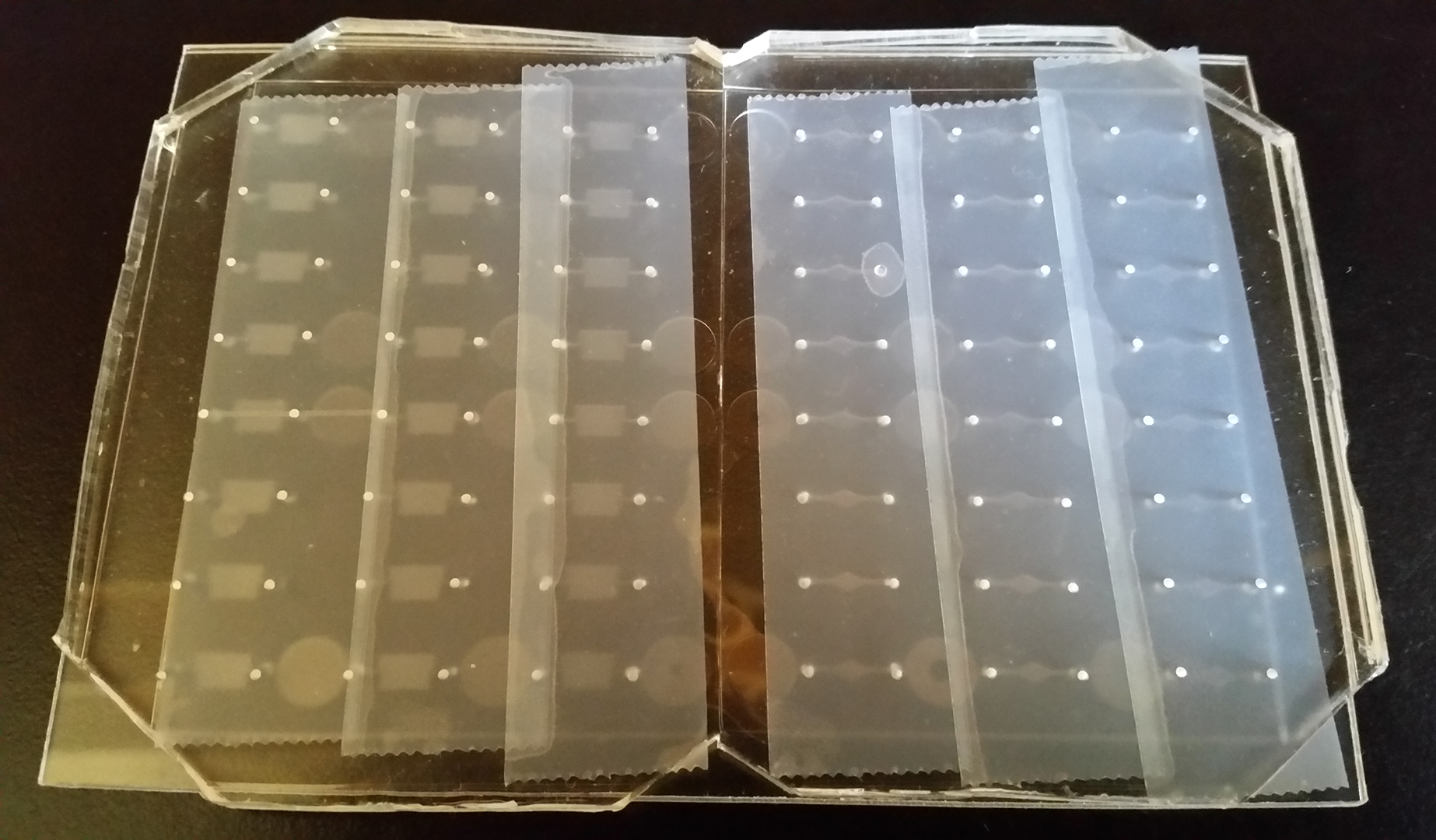
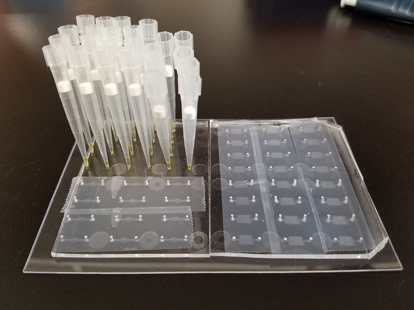
Device Images
Motivation
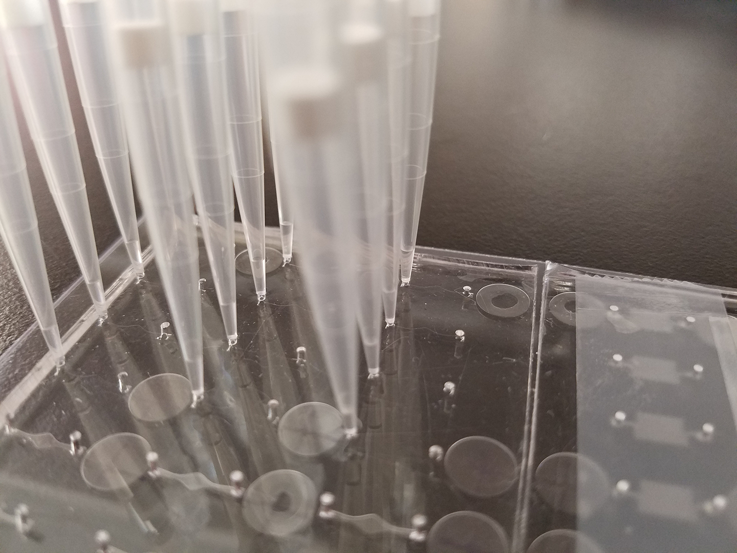
An ELISA (enzyme-linked immunosorbent assay) is a well-established technique to measure analytes; however, several disadvantages of the technique include reagent costs and tedious pipetting.
In this regard, would it be possible to leverage and adapt the Hughes Laboratory’s microfluidic devices for use with ELISA?
Specifically, the use of microfluidics would decrease the amount of
required reagent and, thereby, both the cost and pipetting required.
Benefits
The device poses not only as a reduction in costs and pipetting, but also familiarity with known
technology (microfluidics) but applied in a new application (ELISA). The benefits above stand to
ultimately facilitate the further adoption of ELISA into the workflow of the Hughes Laboratory.
Design Goals
I established the follow design guidelines, each followed by my reasoning:
-
Adapt the design of the Hughes Laboratory’s current microfluidic devices.
A familiar design reduces the time required by researchers to learn how to fabricate the new device.
-
Minimize the costs needed to fabricate one device.
The device must optimize the limited budget I had available, a maximum of $200 for any additional materials not already found within the Hughes Laboratory.
-
The device must be analogous to a standard 96-well plate used with ELISA.
The device must be compatible with the microscopy equipment currently used within the Hughes Laboratory; new equipment would increase costs and violate the 2nd guideline.
-
The device must be as translucent as possible to maximize the accuracy of absorbency measurements.
ELISA is a technique that depends on microscopy; therefore, opaque materials would only sabotage the purpose of the micro-ELISA device.
-
Minimize the time required to fabricate the device to within 1-2 days. Faster fabrication facilitates maximizing my allotted time on the project: 3 months.
Faster fabrication facilitates maximizing my allotted time on the project: 3 months
Design Results
-
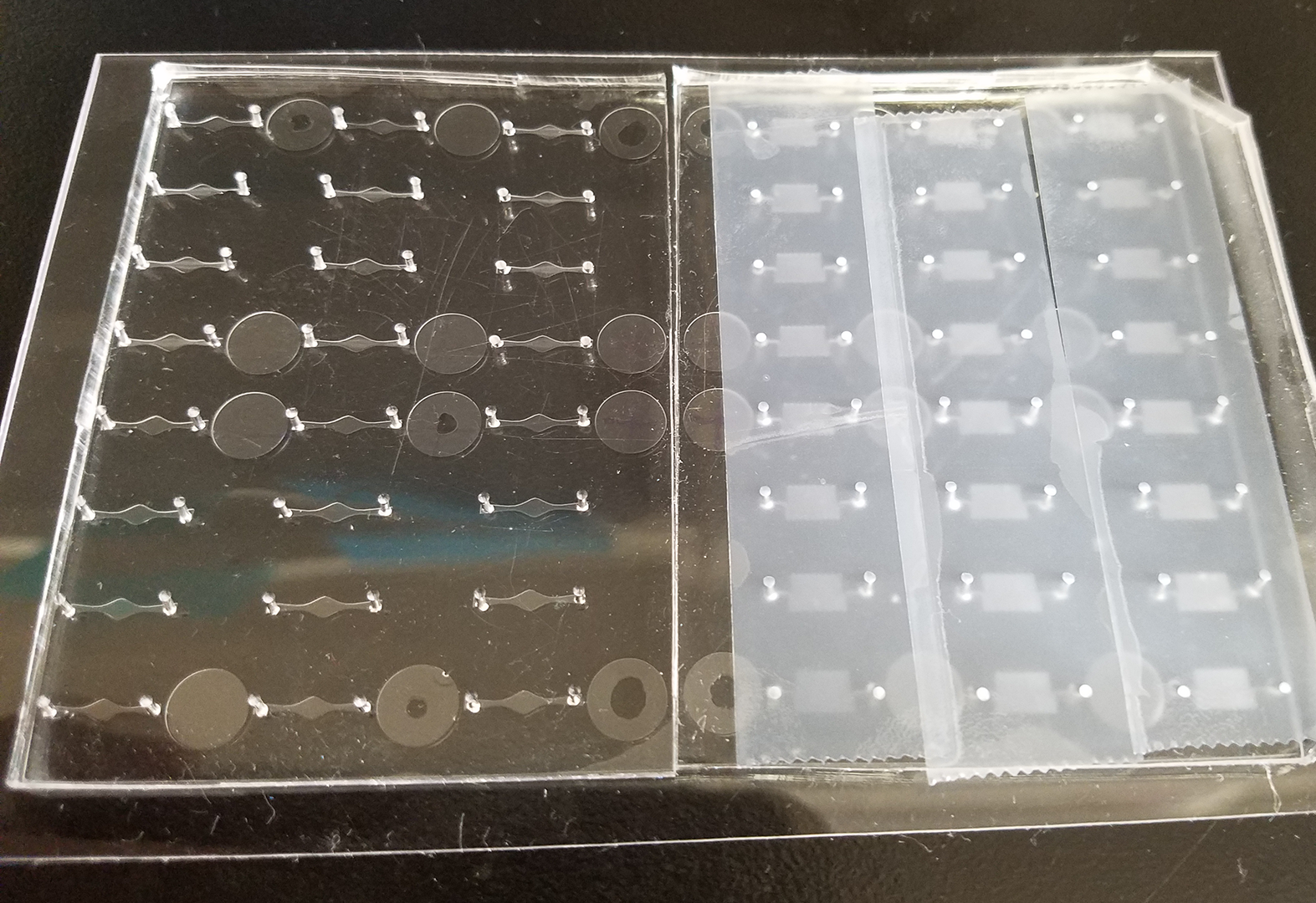
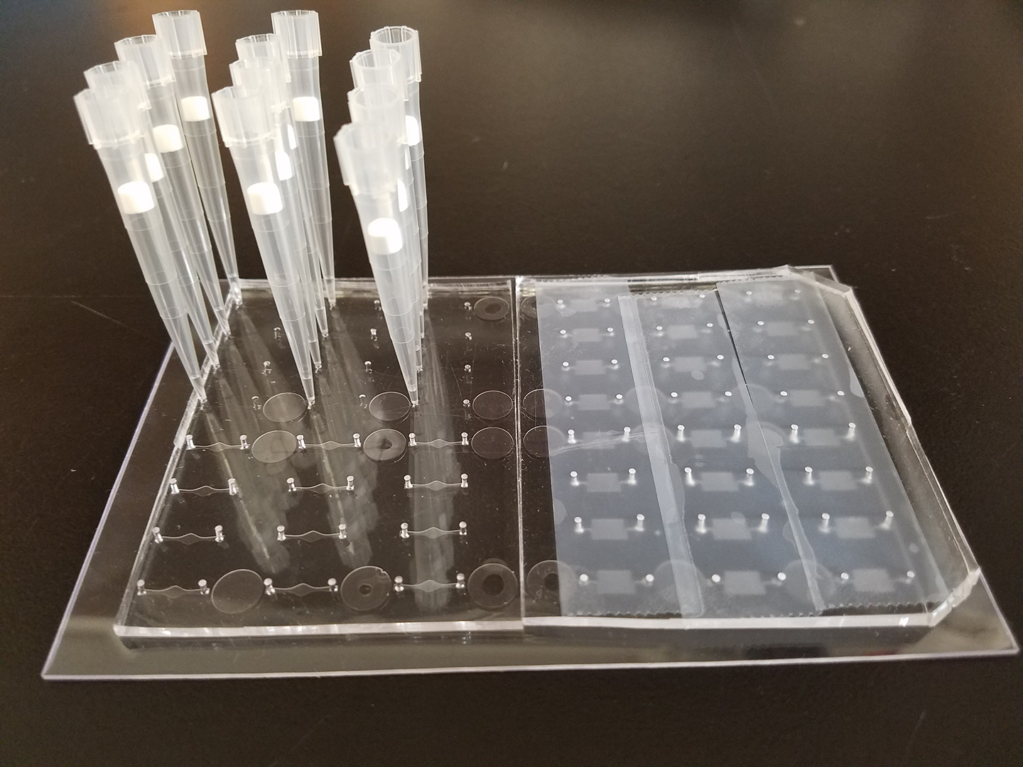
The device combines the PDMS construction of the lab’s current devices with newly designed channels and a polystyrene base sheet.
-
Aside from already available lab materials, the device requires polystyrene sheets and tools to cut the sheets; both are cheap and easily found at arts and crafts stores.
-
The polystyrene sheet is cut to the dimensions of a 96-well plate.
-
The additional polystyrene base sheet and the rest of the device’s construction (PDMS) is both translucent.
-
The device can be constructed within 2 hours and then prepared overnight. Total fabrication time is 24 hours.
-
The straight channels seem to be more effective than the serpentine design.
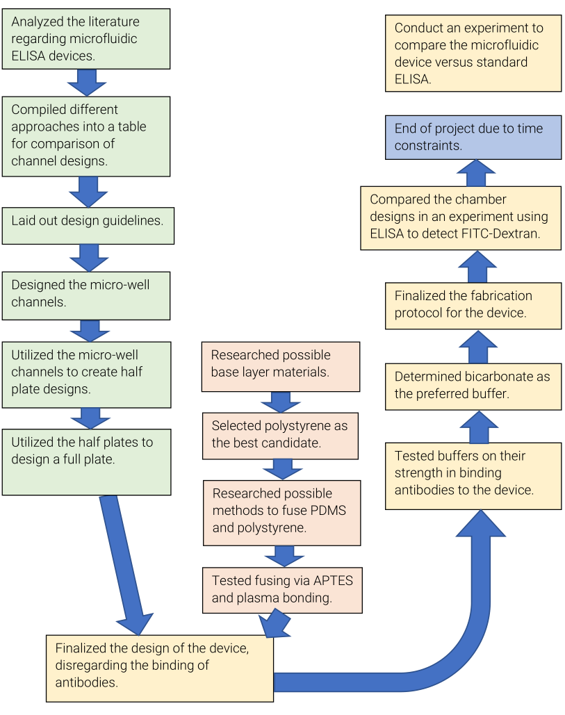
Project Progression
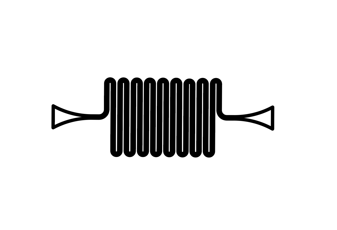
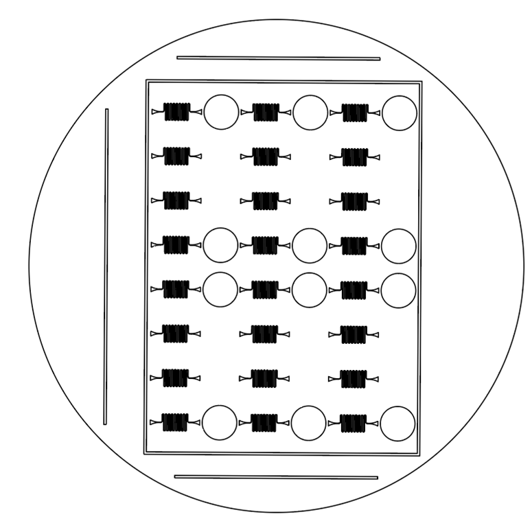
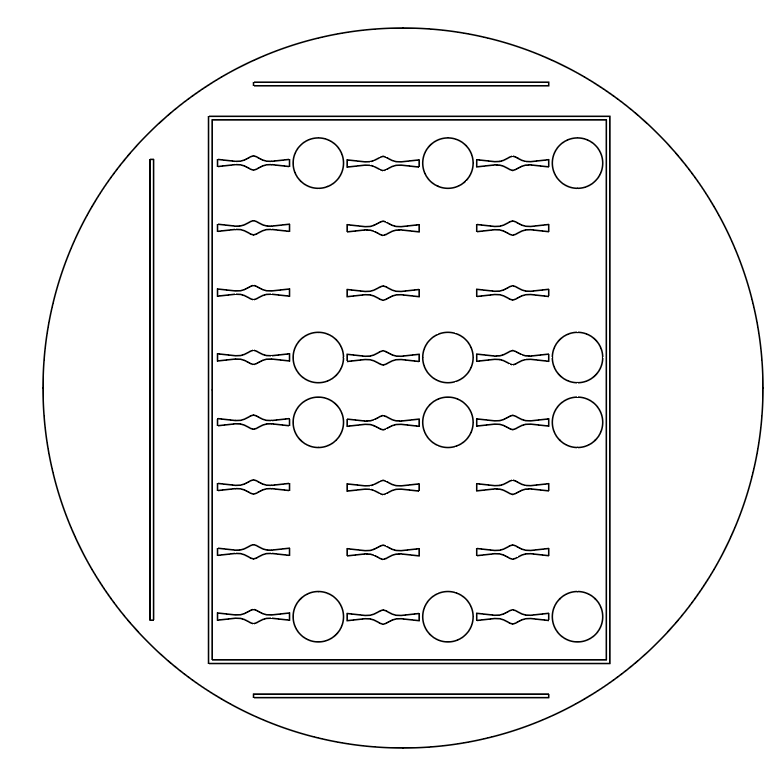
Design of Micro-Well Channels
Several micro-well channels were prototyped within SolidWorks and AutoCad.
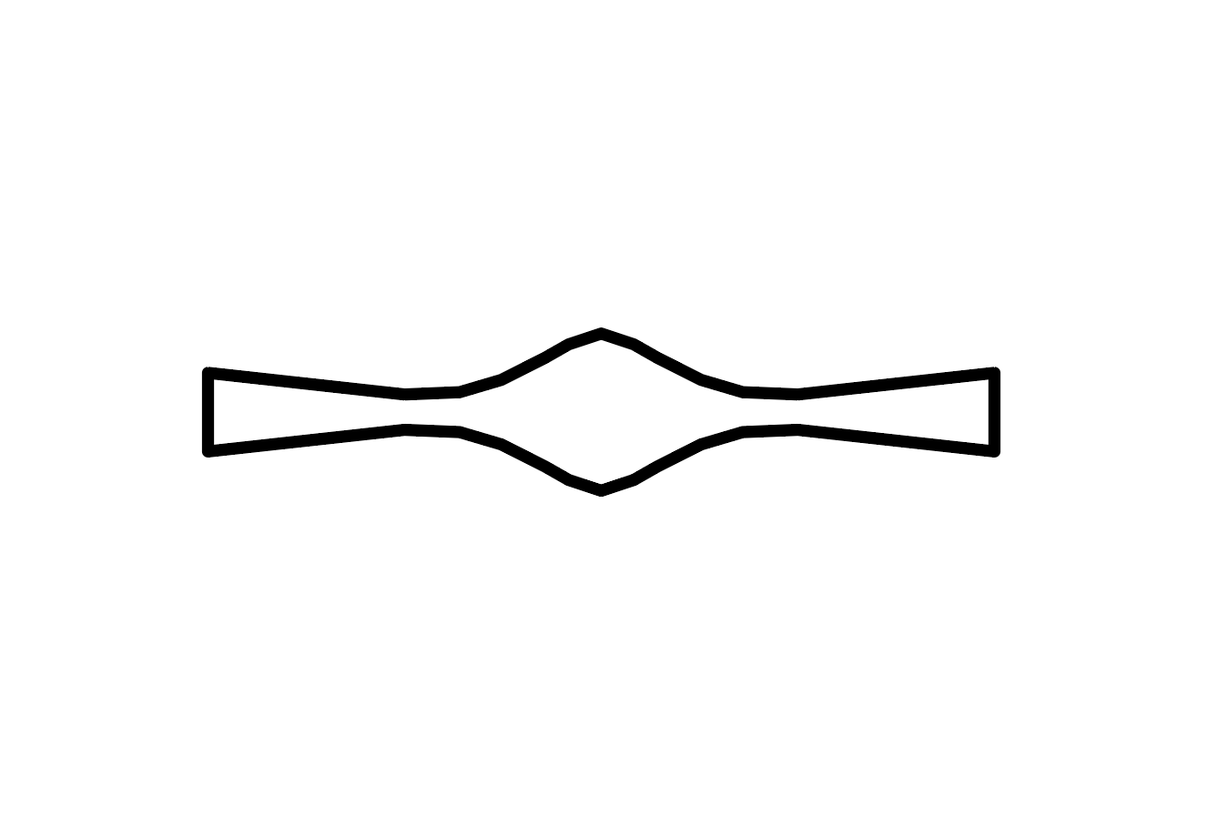
The straight channel was chosen as a starting point, a generic baseline. Conversely, I
designed the serpentine channels as an antithesis to see how narrower chambers and an
increase in total surface area affect the baseline’s behavior.
- Serpentine
- Straight
Design of the Half Plate (Half of 96-Well Plate)
The designs for half of the 96-Well Plates were intended to fit within a standard petri dish.
Additionally, I added guiding lines to 3 sides of the design; because each half of the device is
not symmetrical, the orientation of the halves is critical for correct assembly of the complete
device. The absence of guiding lines indicates where the two halves should be joined.
- Serpentine
- Straight
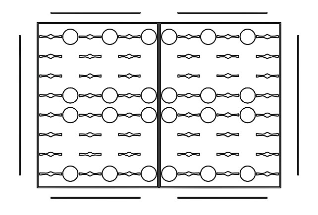
Design of the Full Plate (96-Well Plate)
Plastic molds were created from each of the half plate designs. PDMS can then be poured into the mold to construct half of the device.
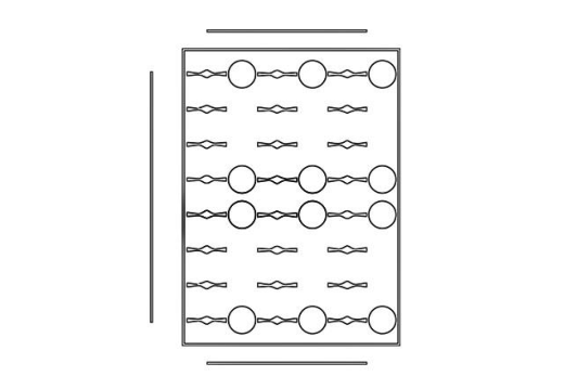
By employing two of the half plate designs, the complete top-layer of the device (analogous to a
standard 96-well plate typically used in ELISA) can be constructed.
The circles found in the designs above serve as landmarks. Each of them exactly corresponds
to a standard well found on a 96-well plate. Therefore, the landmarks ensure that the
polystyrene base layer can be correctly positioned and fused to the device.
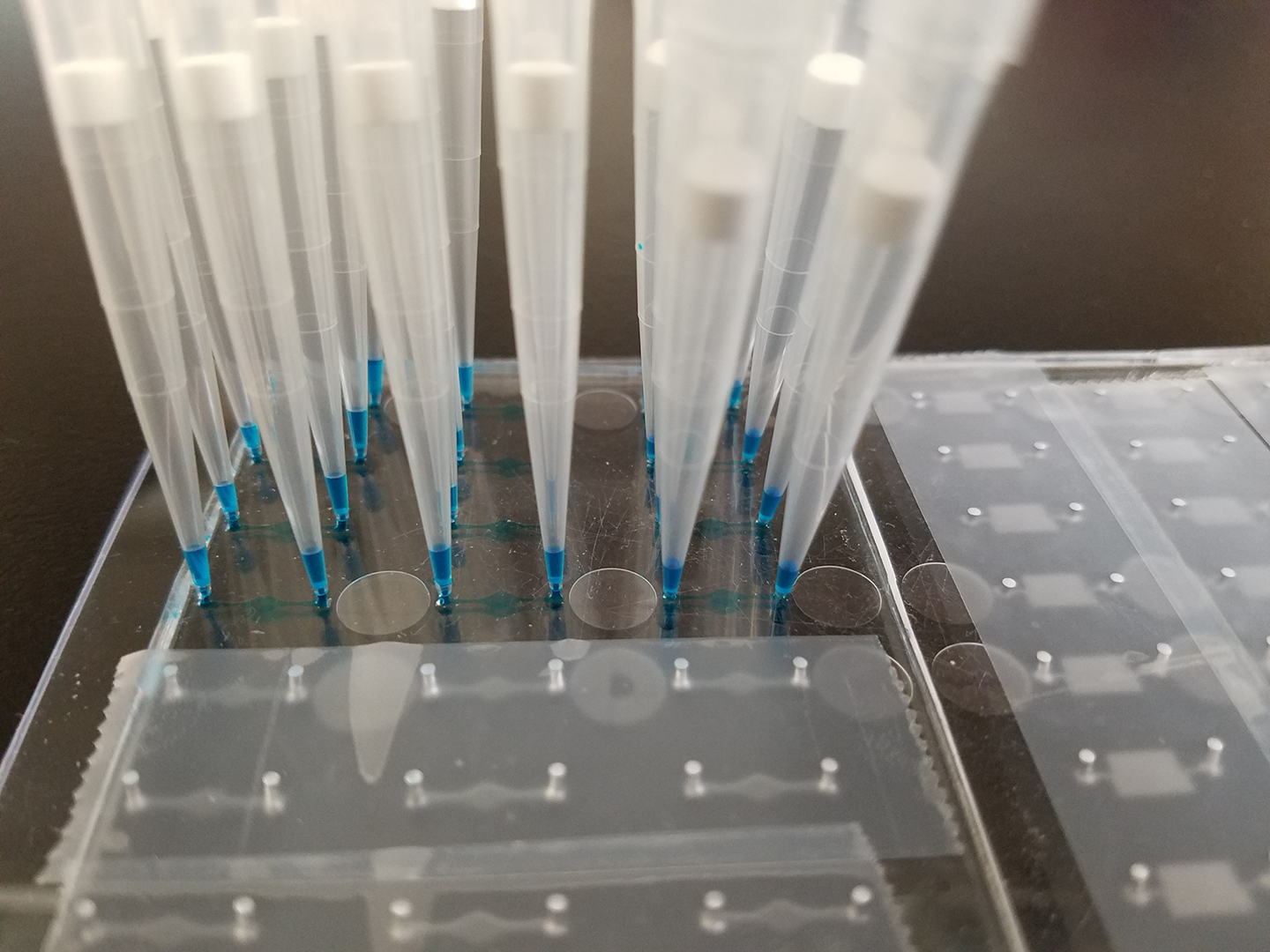
Fabrication
Antibody Binding Test
Goal
Determine which buffer, that is also readily available within the Hughes Laboratory, is most
effective at binding antibodies to the device.
Additionally, determine whether the device
is capable of ELISA as the technique requires the binding of antibodies.
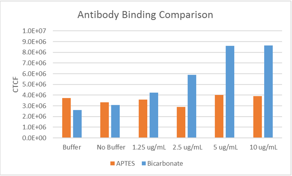

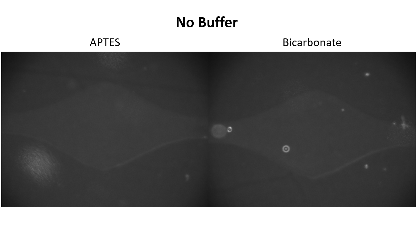
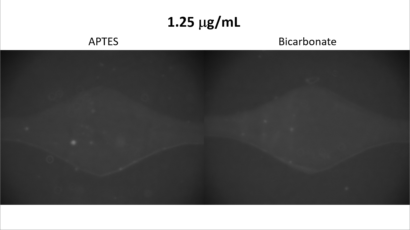
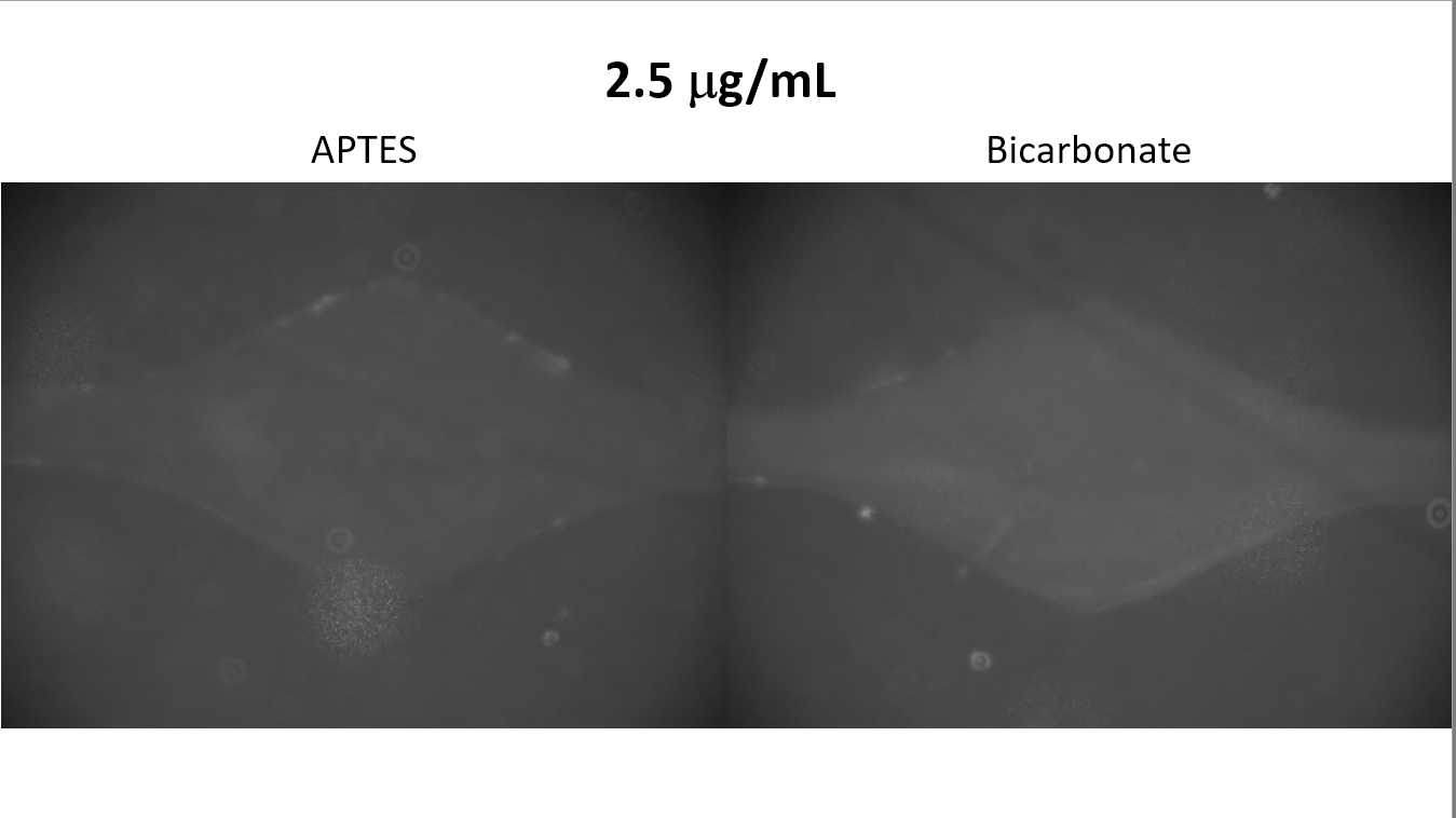
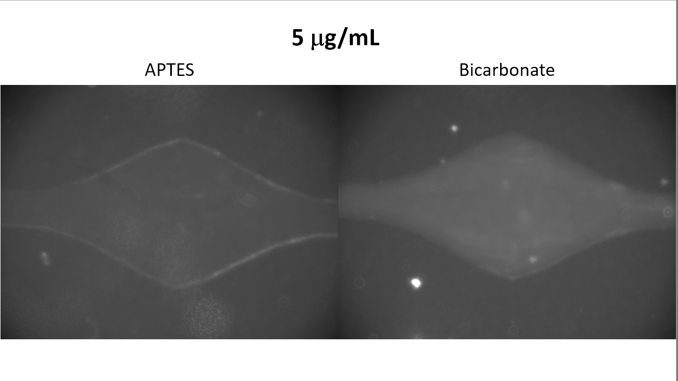
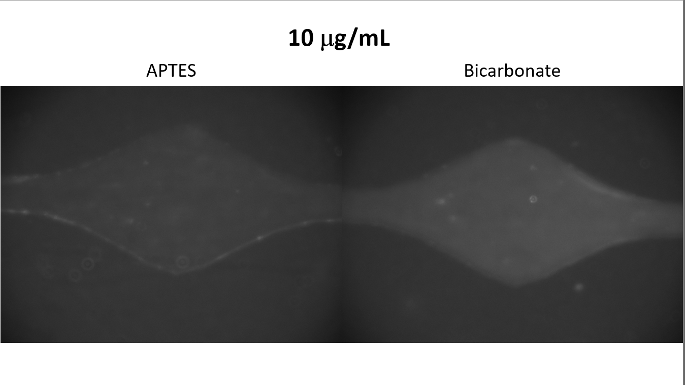
The results suggested that a bicarbonate buffer yields the greatest binding strength and
confirmed that use of ELISA is possible.
Channel Comparison
Goal
Determine which channel design is more effective with the ELISA technique.
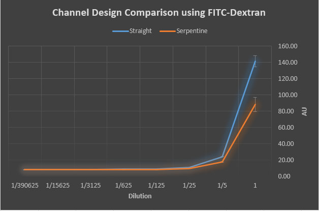
Micro-wells with the straight channel returned greater absorbency readings, suggesting that the
straight design is more effective.